Working Principle of Mechanical Expansion of Welded Steel Pipes

Working Principle of Mechanical Expansion of Welded Steel Pipes

On this page
Abstract: The definitions and working principles of mechanical expansion and hydraulic expansion of welded steel pipes are elaborated. Combined with production practice, the similarities and differences between the two are analyzed from the perspective of process technology, and relevant suggestions are put forward for selecting the two expansion equipment types.
 

Introduction

With the rapid development of oil and gas extraction on land and sea, the manufacturing process requirements for pipeline steel pipes are increasing. The steel pipe expansion process is a standard requirement in steel pipe manufacturing. The purposes of the expansion process are as follows:
  • Correcting the uneven deformation of the steel pipe during the forming and welding process so that the diameter, roundness, and straightness of the steel pipe can reach the required accuracy. 
  • Eliminating the residual stress of the pipe body caused by the compression process of the forming machine, improving the stress distribution, and enhancing the overall mechanical properties of the steel pipe.
  • Eliminating the residual stress in the weld caused by welding, and avoiding hydrogen embrittlement and hydrogen-induced cracks.
 
There are five types of steel pipe expansion machines, including hydraulic expansion machines, pneumatic expansion machines, mechanical expansion machines, electromagnetic expansion machines, and roller expansion machines. Hydraulic expansion machines are highly efficient and precise. Pneumatic expansion machines use compressed air for pipe expansion. Mechanical expansion machines use physical force applied through mechanical means, such as rollers or mandrels, to expand welded pipes. Electromagnetic expansion machines utilize electromagnetic forces for expansion and are sometimes used for specialized applications or high-precision work. Roller expansion machines use a set of rollers to expand pipes, ideal for pipes that require uniform expansion or continuous processes. These steel pipe expansion machines are crucial in the production chain of welded steel pipes. They accurately modify pipe dimensions, ensuring compliance with industry standards and contributing to overall operational efficiency within manufacturing facilities.
 

1. Definition and Working Principle of the Two Expansion Processes

1.1 Definition of the Two Expansion Processes

The mechanical expansion process involves expanding the steel pipe in sections using a mechanical expansion head. The expansion head comprises a group of conical wedges. This method is a block and segmented punch rigid expansion process.

The hydraulic expansion process uses high-pressure emulsion as the pressure transmission medium, with an external mold to limit the size after expansion, expanding the steel pipe from the inside in a single operation. This is an integral die flexible expansion process. Both processes are generally categorized as mechanical expansion methods.
 

1.2 Expansion Principle

1.2.1 Mechanical Expansion Principle
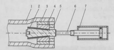
The mechanical expansion principle is illustrated in Figure 1. The oil cylinder pulls the expansion taper head (2) to the right. The expansion taper head (2) pushes the inclined block (4) and the mold (3) to expand. When the set size is reached, the expansion taper head (2) moves to the left, and the inclined block (4) and the mold (3) shrink to complete the expansion of one step. After the steel pipe (1) moves one step, the action is repeated until the entire length of the steel pipe is expanded.

mechanical expansion
1. steel pipe 2. expansion head 3. expansion mold 4. inclined block 5. fixed retaining ring 6. connection (expansion taper head and oil cylinder) mechanism 7. oil cylinder
Figure 1 Schematic diagram of mechanical expansion
 
1.2.2 Principle of Hydraulic Expansion
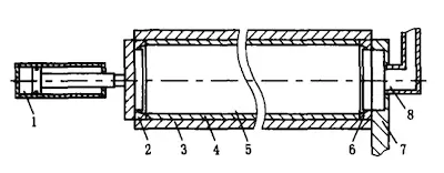
The principle of hydraulic expansion is illustrated in Figure 2. The two ends of the hydraulic expansion machine seal the steel pipe, the outer mold wraps it, and the high-pressure emulsion is injected from one end. The high-pressure emulsion expands the steel pipe until it is close to the outer mold. As the steel pipe expands radially, one end of the hydraulic press extends to prevent water leakage during the process. Once the pressure is maintained for the set time, the expansion process is complete.

hydraulic expansion
1. Thrust cylinder 2 2. Tube end seal 3. External mold 4. Steel pipe 5. High-pressure emulsion 7. Tube end baffle 8. High-pressure water injection pipe
Figure 2 Schematic diagram of hydraulic expansion
 

Nickname*:
E-mail*:
Rate*:
Comments*:


About the author
Teresa
Teresa
Teresa is a skilled author specializing in industrial technical articles with over eight years of experience. She has a deep understanding of manufacturing processes, material science, and technological advancements. Her work includes detailed analyses, process optimization techniques, and quality control methods that aim to enhance production efficiency and product quality across various industries. Teresa's articles are well-researched, clear, and informative, making complex industrial concepts accessible to professionals and stakeholders.