Chromium-molybdenum alloy steel is a high-strength, corrosion-resistant material commonly used in manufacturing critical components such as high-temperature, high-pressure vessels and autoclaves. In delayed coking units, chromium-molybdenum alloy steel pipes must endure high temperatures and pressures while ensuring a long service life. Consequently, improving the welding quality of these pipelines has become a pressing issue. This paper focuses on the welding techniques and optimization strategies for Cr-Mo alloy pipes in delayed coking units. By applying practical methods and effective solutions, this study aims to provide a more scientific and efficient approach to the use of delayed coking units.
During the prefabrication and cutting of chromium-molybdenum alloy pipelines, each component’s identification must be verified and marked to ensure accuracy. Carbon steel can be processed by machining or flame cutting, while chromium-molybdenum alloy steel is better suited for machining. If flame cutting is used, any slag and oxide layers should be removed by grinding to achieve a smooth, metallic finish. When working with chromium-molybdenum alloy steel, 100% surface inspection is required. Mechanical techniques must be used to prepare the grooves on chromium-molybdenum alloy furnace tubes.
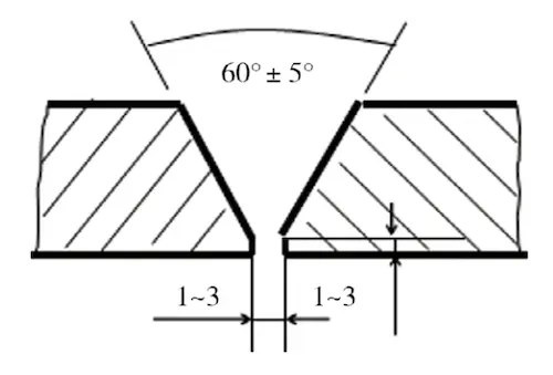
In accordance with GB50236-2011, Construction and Acceptance Specifications for Field Equipment and Process Pipeline Welding Engineering, to ensure welding quality, the wall thickness of furnace tubes and pipelines should not exceed 25 mm, and the groove design of the connection must meet specified requirements. For connections with V-shaped grooves, reference can be made to Figure 2.

Figure 2 V-shaped groove
Before starting work, the groove and adjacent parent material should be inspected to confirm there are no defects, such as cracks, scaling, damage, or burrs, and that the groove dimensions meet the drawing specifications. The groove surface and a surrounding 20mm area should be free of oil, rust, paint, and other debris, then finely polished with a grinding wheel to achieve a metallic sheen.
Prior to assembling the furnace tube, ensure that the tube’s straightness is within 1/1000. If the tube length is 6 meters or less, the overall curvature should not exceed 4mm; for lengths over 6 meters, it should not exceed 8mm. After assembling the furnace tube, the tack welding seams must meet the following requirements:
- Tack welding procedures must adhere to standards, including a welding seam length of 10-12mm and a welding seam height of 2-4mm.
- Forced welding techniques should be avoided.
- Tack welding seams must be evenly distributed around the pipe.
- When welding, the starting point should be positioned between two tack welding seams, ensuring complete fusion of the tack welding seam without any nodules or defects. If any cracks or defects are found, they should be repaired immediately.
- Both ends of the welding seam should have a smooth slope to minimize stress concentration.
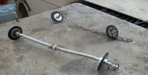
Before positioning welding, spot welding should be performed according to specified parameters, with at least three spot welds spaced a minimum of 20mm apart. This helps prevent cracking in the positioning welding seam. After completing positioning welding, inspect the spot welding seams immediately and repair if any issues occur to maintain joint quality. When welding, introduce the arc into the welding channel rather than on the surface of the welded part. To ensure the welding seam’s quality, argon arc welding should be used, with argon purity above 99.99%. Water-soluble backing or specialized tooling is also recommended to reinforce the weld (Figure 3).

Figure 3 Argon arc welding
Before butt and fillet welding on 1Cr5Mo and 1Cr9Mo, preheat them to 250–350°C. During preheating, ensure both sides of the groove are evenly heated, with the heating zone extending at least five times the material’s wall thickness and no less than 100mm to prevent partial overheating. Insulate the 100mm area beyond the heating zone to maintain a consistent temperature.
To ensure welding quality, a designated welding enclosure must be set up at the site, with both ends of the furnace tube securely closed to prevent external wind and rain intrusion. Additionally, for safety, arc strikes and current testing on coal surfaces are strictly prohibited, and the tensile strength of chromium-molybdenum alloy steel and other materials must reach at least 540MPa. No arc scratches or other surface defects should appear on the welded pieces. When the material reaches the required preheating temperature, welding should be conducted immediately, maintaining a consistent temperature so all welding seams can be completed in one session. If an issue arises for a welding seam requiring heat treatment, welding must be halted, and the weld post-heated to prevent cracking. For multi-layer welding, adjust the interlayer temperature to slightly exceed the preheating temperature and ensure proper separation between weld layers. After completing each welding seam, perform PMI (Positive Material Identification) spectroscopic analysis to verify that the chemical composition meets the required standards.
The welding heat treatment of Cr-Mo alloy pipes in the delayed coking unit requires sanding or grinding the surface to remove the oxide layer and contaminants. Additionally, the pipeline must be pickled or treated with an alkaline wash before proceeding with welding. For welded joints made from chromium-molybdenum alloy steel and other steels with a tensile strength exceeding 540MPa, heat treatment must be performed immediately after welding to ensure quality. If immediate treatment is not possible, the welding area should be uniformly heated to a temperature range of 300–350°C and then cooled. The post-welding heat treatment must align with the specified insulation parameters, as shown in Table 3.
Table 3 Heat treatment parameters
| Steel Grade |
Temperature (°C) |
Constant Temperature Time (min/mm) |
Minimum Constant Temperature Time (h) |
Hardness Requirement (HB) |
| 1Cr5Mo |
750 - 780 |
2.4 |
1 |
≤241 |
| 1CrSMo |
750 - 780 |
2.4 |
1 |
≤241 |
During the heating process, the heat treatment area must extend at least three times the width of the welding seam, and a minimum of 25mm. In the 100mm area beyond this zone, insulation must be applied, and both ends of the pipe should be sealed. As shown in Figure 4, to ensure proper heat treatment, the heating and cooling rates must comply with the following requirements:
(1) When the temperature reaches 300°C, the heating rate should not exceed 5125/T (°C/h), and the cooling rate should not exceed 220°C/h.
(2) During the constant temperature phase, all measured temperatures must remain within the required heat treatment range, with a maximum variation of 50°C.
(3) During constant temperature conditions, the cooling rate should be calculated as 6500/T (°C/h), and should not exceed 260°C/h. Once the temperature drops to 300°C, natural cooling may be used. T represents the actual wall thickness of the pipe (mm).
This paper presents an in-depth study of the welding process for chromium-molybdenum alloy steel pipes in the heating furnace of a delayed coking unit. Through experiments and analysis, it was determined that controlling the interlayer temperature and welding energy is crucial to maintaining stable and reliable welding quality. To ensure the material properties after welding meet design specifications, careful management of heat treatment and cooling processes is essential. Additionally, attention must be given to surface cleaning and pretreatment before welding to prevent defects or cracks. This paper also suggests improvements, such as adopting a combined welding method and optimizing welding parameters, to enhance welding efficiency and reduce costs.

