Abstract
Large-diameter, thick-walled low-temperature carbon steel pipes (A333-Gr6) are highly susceptible to cold cracking during welding due to the combined effects of hardenability, residual stress, and diffusible hydrogen. Cracks must be removed through grinding or carbon arc gouging, followed by well-defined welding repair procedures. To prevent the recurrence of cracks, key control measures include preheating before welding, thorough cleaning of the weld area, selecting appropriate groove designs, ensuring proper tack welding, securing workpieces with fixtures, minimizing welding interruptions, and performing post-weld heat treatment to reduce hydrogen-induced cracking and relieve residual stresses. These measures effectively mitigate the risk of cracking.
As global environmental concerns grow, developing a clean, low-carbon, safe, and efficient energy system has become a priority for many nations. Liquefied natural gas (LNG) is increasingly recognized as a clean and efficient energy source. Since natural gas must be liquefied at cryogenic temperatures for transportation, LNG process pipeline materials must possess exceptional low-temperature resistance. A333-Gr6 is the primary material used in a specific LNG project due to its excellent toughness and strength at low temperatures. However, it is prone to cracking during the welding of large-diameter pipelines. This paper explores the causes of crack formation and presents strategies for controlling the welding process to prevent crack recurrence in LNG pipelines.
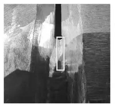
The pipeline material used in the core module of an LNG project is A333-Gr6, a low-alloy steel recognized for its toughness and strength at low temperatures. Table 1 details the chemical composition of A333-Gr6. As shown in Table 1, the carbon equivalent (Ceq) of A333-Gr6 is 0.5215%, contributing to its high hardenability and susceptibility to cold cracking. Therefore, preheating is required before welding. During a routine inspection, cracks were detected at the root of the tack weld in a 600 mm nominal diameter pipeline with a wall thickness of 46.02 mm (SCH120), as shown in Figure 1. After welding, radiographic testing (RT) identified additional cracks in the weld. Weld cracks impair mechanical properties and surface quality, posing significant safety risks during production and operation.

Figure 1: Location of cracks at the root of the tack weld
Table 1: Chemical Composition of A333-Gr6
|
Element |
Content (%) |
|
C |
≤ 0.30 |
|
Mn |
0.29 – 1.06 |
|
P |
≤ 0.025 |
|
S |
≤ 0.025 |
|
Si |
≥ 0.10 |
2. Factor Analysis of Weld Cracks in A333-Gr6 Pipelines
Weld cracks in carbon steel pipelines are typically classified as hot cracks, reheat cracks, cold cracks, or lamellar tearing. In large-diameter, thick-walled, low-temperature carbon steel pipes, cold cracks are the most common type. These cracks are primarily caused by three factors: hardenability, residual stress, and diffusible hydrogen. The carbon equivalent (Ceq) of A333-Gr6 is 0.5215%, indicating moderate hardenability. Therefore, preheating is necessary during welding to minimize the risk of cold cracking, and maintaining the correct preheating temperature is essential for effective control. Welding procedure specifications (WPS) for carbon steel typically require a minimum preheating temperature of 30°C. For pipelines with a wall thickness greater than 25 mm, the preheating temperature should be increased to 95°C. For weld repairs, the preheating temperature should be 20–30°C higher than the WPS minimum.
As the project involves large-diameter, thick-walled pipes, the preheating requirements are more stringent. Common preheating methods include oxy-fuel hotplates, electromagnetic induction heaters, and resistance heaters. Hotplates are commonly used for their ease of operation and flexibility in varying worksite conditions. However, because the project requires annular preheating for large-diameter, thick-walled pipes, resistance heating is employed. The preheating zone extends 75 mm on both sides of the weld groove. Heating equipment is positioned around the weld groove for preheating.
After preheating, the heating should be paused for at least one minute before measuring the temperature. Common temperature measurement devices include infrared thermometers, contact thermometers, and temperature indicators. Due to the elliptical shape of the pipe’s outer wall, infrared thermometers may yield inaccurate readings. Thus, a contact thermometer is typically used for measuring preheating temperature. As the construction site is outdoors, setting up electric heating tools requires substantial infrastructure, leading to high initial preparation time and costs. Additionally, due to the pipeline’s wall thickness, the construction team opted to use hotplates for preheating to expedite the process. This method primarily heats the steel surface, making it difficult to control the preheating temperature precisely and potentially resulting in insufficient internal heating.
Welding involves non-uniform heating and cooling, causing inconsistent expansion and contraction of the pipeline within a fluctuating temperature field. During welding, the temperature in the heat-affected zone near the molten pool rises rapidly, resulting in partial melting. The heated section of the pipe expands, while the weld metal contracts during solidification. Due to the large diameter, thick walls, and high structural rigidity of the pipeline, the weld is constrained by adjacent materials with lower temperature and expansion rates during thermal cycling. Cold cracking occurs when the restraint stress exceeds the material's critical threshold. Improper welding techniques can contribute to stress concentration and crack formation. For example, failure to clean interlayers, improper staggering or polishing of arc start and end points, and irregular weld formation can contribute to stress concentration. On-site observations indicate that when the arc termination point coincides with the weld bead, shrinkage cavities form. If welding continues, these defects may propagate into cracks.
Hydrogen accumulation in the weld typically results from insufficient preheating, inadequate heat treatment, or incomplete removal of surface contaminants. Moisture and oil present on or within the pipeline decompose under arc heat, releasing hydrogen. After welding, as the pipeline cools, the hydrogen diffuses into surrounding areas. If cooling occurs too rapidly, the diffused hydrogen cannot escape, necessitating multi-layer welds for thick-walled, large-diameter pipelines. Proper heat input ensures that the weld cools at a controlled rate, allowing hydrogen to escape. Conversely, insufficient heat input leads to hydrogen accumulation, while excessive heat input can cause grain embrittlement. Under additional stress, microcracks may develop in the weld.
In summary, welding cracks result from multiple interacting factors. If left uncontrolled, they can significantly affect weld quality and compromise the commissioning and operation of equipment.
Weld repair requires welding engineers to develop procedures in accordance with the owner's project specifications. These procedures must be submitted for approval prior to the commencement of any repair work. Once the repair plan is approved, implementation can proceed. Quality inspectors must ensure that all on-site repairs, including crack removal, adhere strictly to the approved procedures. Repairs must comply with procedural requirements. Welding personnel responsible for repairs must undergo additional radiographic testing (RT) of the repaired welds. The results of these tests must be documented, and corrective actions taken as necessary.
Before initiating repairs, the construction site supervisor must conduct a pre-shift briefing with the repair team. If necessary, quality inspectors and the owner should also be invited to attend. During this briefing, key quality and safety considerations must be highlighted. A self-check should also be conducted to ensure that the Welding Procedure Specification (WPS) and relevant repair guidelines are clearly posted in the work area. The quality inspection team must be informed of the repair schedule and progress, and the repair plan submitted to the owner in advance.
Cracks in large-diameter, thick-walled pipes include tack weld cracks and post-weld cracks. As tack welds in carbon steel become a permanent part of the final weld, any cracked tack welds must be ground and removed. In contrast, non-ferrous large-diameter pipelines use bridging blocks made from the same material as the base metal for tack welding. These blocks are ground and welded sequentially during final welding to prevent tack weld cracks.
Cracks that appear during or after welding must be removed by grinding or carbon arc gouging. All gouged areas must be ground carefully to eliminate any residual carbon contamination near the defect. It is crucial to avoid damaging the base material while removing defective welds. Surface cracks must be removed by grinding, ensuring that the grinding depth does not exceed the maximum allowable wall thinning. If necessary, ultrasonic thickness measurement (UTM) must be used to verify compliance with the required wall thickness. For example, A333-Gr6 allows a maximum wall thickness reduction of 12.5% of the original base material thickness. After grinding, the repaired surface must be inspected using non-destructive testing (NDT) methods, such as magnetic particle testing (MT) or penetrant testing (PT), to verify defect removal.
Internal defects must be removed systematically, starting at least 25 mm from the defect's edge (or 50 mm for cracks) and progressing inward. The process should be repeated symmetrically from the opposite side until the defect is completely eliminated. For materials with impact toughness requirements, at least 5 mm of material should be removed from both sides of the heat-affected zone (HAZ) and the base metal. The final repair area should transition smoothly to the surrounding material, and the depth and width of the removed defect must be documented for the owner's inspection and project records.
Any defect removal slot must be at least 50 mm in length, and adjacent defects less than 100 mm apart must be treated as a single continuous defect. Once the welding crack defect is removed, it must be verified that the defect has been completely eliminated before re-welding. The surface of the repair area must be thoroughly cleaned. The WPS used for repair welding must match the original welding procedure. If the original welding process cannot be fully replicated due to construction constraints (e.g., pipeline orientation preventing submerged arc welding), an alternative repair welding method, such as gas tungsten arc welding (GTAW) followed by gas metal arc welding (GMAW), may be used, subject to owner approval.
The preheating temperature for repair welding must exceed the original WPS preheating temperature by 30°C. Once preheating is complete, the repair welding process can begin. A maximum of two repairs is allowed for the same weld area. Any additional repairs beyond this limit require owner approval; otherwise, the affected pipe section must be replaced. For materials with specific post-weld heat treatment (PWHT) requirements, such as wall thicknesses exceeding 25.4 mm, PWHT must be reapplied after repair welding and successful visual inspection.
4. Welding Control Measures
According to the analysis conducted above, reducing weld hardenability, minimizing residual stresses, and eliminating diffusible hydrogen are effective in reducing or preventing the occurrence of welding cracks. The following control measures aim to optimize the welding process and prevent crack recurrence, considering actual working conditions.
(1) Select Highly Skilled Welders
The skill level of the welder is a critical factor in determining welding quality. Highly skilled welders achieve a first-time pass rate above 98% in pipeline welding, while less experienced welders may have a pass rate below 80%. Experienced welders can accurately identify and prevent welding defects, quickly diagnose their causes, and promptly adjust welding parameters or implement corrective actions. Employing welders with professional certifications and proven experience greatly reduces the risk of welding cracks and enhances the consistency of welding quality.
(2) Ensure Uniform Preheating Before Welding
For pipes with a wall thickness exceeding 40 mm, the preheating temperature must be at least 95°C, while the interpass temperature should not exceed 250°C. Oxyacetylene flame heating should be avoided during preheating. Resistance or induction heating is recommended to ensure uniform heating of the pipe's inner and outer walls. Constant monitoring of the pipe wall temperature is required during heating to ensure compliance with preheating requirements, minimizing the impact of thermal gradients on weld quality and reducing the risk of cracks.
(3) Keep the Welding Area Clean
Before assembly, a carbon steel grinding wheel should be used to clean at least 25 mm of the groove's interior and exterior, thoroughly removing paint, grease, rust, and other contaminants to prevent welding defects. During welding, the interlayer weld surface must be kept clean, and any oxide scale formed after CO₂ shielded welding should be promptly removed. The surface should be gently tapped with a welder’s hammer and then polished with a grinder. Weld joints and any irregular excess height on the interlayer welds should be blended smoothly to reduce stress concentration and minimize the risk of cracks.
(4) Proper Selection of Groove Design
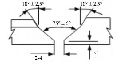
For thick-walled pipes, particularly those with a wall thickness greater than 40 mm, a U-shaped groove is recommended over a V-shaped groove (Figure 2). The U-shaped groove effectively reduces the volume of the molten pool and weld shrinkage, thereby minimizing welding stress and improving joint quality and crack resistance.

Figure 2: U-shaped Groove
(5) Strictly Control Positioning Welds
Positioning welds on carbon steel pipelines are generally not removed during subsequent welding, so their quality must be ensured at the assembly stage. Due to the brief duration of positioning welding and the limited heated area, a significant temperature gradient can develop, increasing the risk of cracks. As such, the area around the positioning weld should be preheated to no less than 95°C. Each positioning weld must be a minimum of 50 mm in length, with a thickness between 6 and 8 mm, and evenly distributed around the circumference. At least eight positioning welds should be made on-site to ensure the pipeline’s bearing capacity and prevent cracking before final welding.
(6) Ensure High Assembly Quality
When connecting pipes to each other or to accessories, temporary supports, hinges, or tension belts should be used to secure the joints and prevent cracks in the positioning welds due to structural stress. Hammering should be avoided when removing temporary securing components. Temporary supports welded to the parent material should be polished and blended seamlessly after removal. Penetration testing (PT) must be performed, if required, to verify the absence of residual cracks. During assembly, misalignment should be avoided, and any misalignment of the inner and outer walls of the groove should be corrected to meet construction specifications. If the wall thickness differential between pipes exceeds 3 mm, edge trimming should be performed, with the trimming length at least four times the thickness difference to ensure welding quality.
(7) Welding Process Monitoring
During the initial phase of welding, comprehensive process monitoring should be implemented to ensure strict adherence to the welding procedure specification (WPS). This includes controlling preheating temperature, welding current, voltage, and interlayer temperature. A designated individual should continuously monitor all welding parameters and record them in the "Welding Parameter Record Table" for reference. Once welding quality stabilizes, random inspections can be conducted to verify ongoing compliance with WPS requirements and maintain long-term welding quality stability.
(8) Optimize Welding Sequence and Reduce Welding Stress
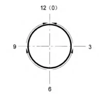
A well-organized welding sequence can effectively reduce welding deformation and residual stress. As shown in Figure 3, the welding sequence for each layer should follow this order:
- Weld 6-9 sections first
- Weld 3-12 sections next
- Weld 6-3 sections next
- Finally, complete the welding of 9-12 sections
For large-diameter pipelines, two welders can work from opposite sides following this sequence to reduce stress concentration and welding deformation, thereby enhancing welding quality. By implementing these welding control measures, the risk of welding cracks is effectively reduced, welding quality in oil and gas field gathering and transportation pipelines will improve, and the long-term safe and stable operation of the pipeline will be ensured.

Figure 3: Pipeline welding sequence