When the
steel pipe expands radially, it will shrink in the axial direction to compensate for the loss in wall thickness during expansion. During mechanical expansion, there is friction between the outer surface of the mold and the inner surface of the steel pipe, and this friction opposes the direction of the axial contraction force of the steel pipe. When parameters such as material, wall thickness, and expansion rate are set, the ideal axial contraction rate of the steel pipe should be constant. However, when the diameter is expanded, the pipe sections contract from both sides of the mold towards the middle. During contraction, they are affected by frictional resistance. The stress conditions in different sections of the steel pipe will vary within a single expansion step. As the contraction distance increases, the axial deformation of the steel pipe also increases. Therefore, the axial shrinkage within the same expansion step varies. In terms of size, the wall thickness of the steel pipe in the middle section of the mold is the thinnest because shrinkage compensation is minimal; conversely, the closer to the ends of the mold, the greater the shrinkage compensation, resulting in thicker wall thickness. In terms of mechanical properties, this manifests as uneven stress distribution. The hydraulic expander uses the outer mold inclusion method. During contraction, the steel pipe does not make close contact with the inner wall of the outer mold, resulting in minimal friction. Additionally, the axial thrust compensation of the hydraulic press ensures that each section of the steel pipe achieves a uniform shrinkage rate, effectively avoiding errors in axial wall thickness and partial residual stress.
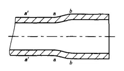
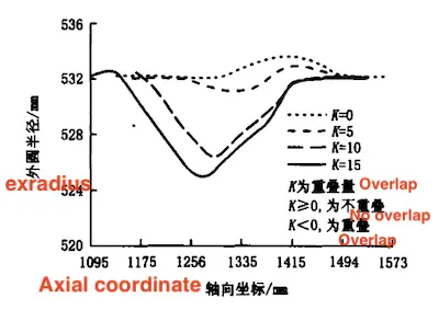
Mechanical diameter expansion uses a segmented diameter expansion process. A joint section (a-b) exists between each pair of diameter expansion steps. The deformation in this section is relatively complex. During the first diameter expansion, the ab section is stretched and elongated, resulting in tensile stress. When the second section a-a' is expanded, the ab section experiences compressive stress. Shortening the elongated pipe section is challenging. During expansion in the a-a' section, the ab section is axially stretched, altering the stress state. The "bamboo joint" phenomenon is likely to occur in this section. If sufficient overlap exists during the two expansions, the ab section will bulge. Without overlap, the ab section will become concave. With appropriate overlap, a combination of bulging and concavity will appear (Figures 3 and 4). The unevenness of section a is evident in the uneven axial direction and wall thickness of the steel pipe surface. In terms of mechanical properties, it manifests as uneven local stress distribution. Because hydraulic expansion is performed in one step, no joint section is present.

Figure 3 Steel pipe diameter change during mechanical expansion

Figure 4 Transition curve of axial overlap zone during mechanical expansion
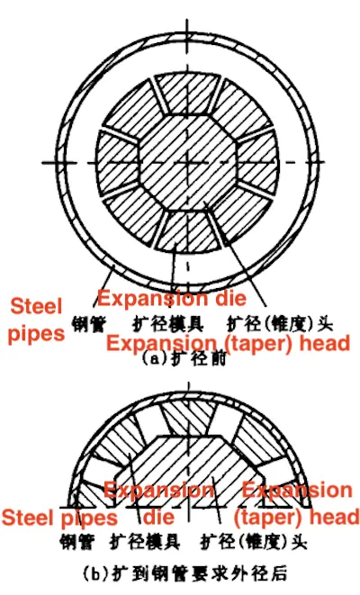
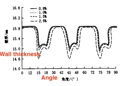
During mechanical expansion, the expansion die employs multiple fan-shaped blocks to expand and support the inner wall of the steel pipe from the cross-section. A gap exists between each pair of fan-shaped blocks, which widens as the mold expands, as shown in Figure 5. The distribution of steel pipe wall thickness at different expansion rates is depicted in Figure 6.

(a) before expansion
(b) after expansion to the required outer diameter of the steel pipe
Figure 5 Schematic diagram of mechanical expansion

Figure 6 Distribution of Wall Thickness Under Different Expansion Rates
During expansion, the contact between the outer arc of the expansion die and the inner wall of the steel pipe generates a frictional force that opposes the tensile stress. Due to friction, the tensile stress at points b and e in the middle of the die block is minimal, while the tensile stress at point a is maximal due to the lack of friction. Visually, the cd segment will have a straight edge (which becomes more apparent when material strength is low and wall thickness is small). The c segment has the thinnest wall thickness and the largest elongation. The elongation of the al segment greatly exceeds the average expansion rate, while the elongation at points b and e in the middle of the die block is the smallest. Due to varying friction and movement distances, the elongation of the al segment and the b segment is variable. Therefore, if the average expansion rate approaches the upper limit, the partial elongation of segment a will exceed standard requirements, reducing the partial plastic reserve of the steel pipe. If the average expansion rate approaches the lower limit, the elongation of points b and e, along with their surrounding areas, will fall short of standard requirements, preventing the achievement of ideal roundness and complete removal of internal stress. The unevenness in wall thickness and elongation affects the uneven distribution of stress in the same circular section. Additionally, the curvature of a typical mechanical expansion mold is designed for a specific wall thickness range. Therefore, the arc segments a and d of each mold, generally differ from the ideal circle. The outer mold for hydraulic expansion is a continuous ideal circle, so these issues do not occur.
Mechanical expansion is a type of rigid punch bulging process. During the expansion process, the raised inner welding seam has a minimal contact area with the expansion die. Therefore, if it is in rigid contact with the die, the inner surface of the welding seam will experience significant contact stress, increasing its surface hardness. Additionally, the steel pipe will shrink axially during expansion, causing the welding seam and the die to move relative to each other under substantial contact stress, generating considerable friction. Excessive friction can cause the weld to partially melt. It is important to avoid hard contact between the welding seam area and the expansion die. Standards stipulate that when using a rigid punch tool for expansion, the welding seam of the steel pipe must not contact the die. The general method used by the mechanical expander is to open a groove in the middle of a specific fan-shaped block (be). This method is employed to avoid hard contact between the die and the welding seam. While this method avoids hard contact between the welding seam and the die, it creates another issue: the welding stress of the welding seam cannot be released.
According to the welding material matching principle, the welding seam strength is generally higher than that of the parent material. Besides the strengthening effect of the welding seam’s excess height, the welding seam strength is much higher than that of the parent material. Considering the friction factor, the tensile stress is minimized. The welding seam does not experience enough tensile stress during expansion, preventing the release of welding stress. If the welding seam has the conditions for delayed cracking, cold cracks may appear during future use, potentially causing significant damage to the pipeline’s safety.
The hydraulic expansion process is a flexible bulging method. The contact state between the welding seam and the mold is similar to that of the parent material. The welding seam contacts the mold only after the expansion is completed, with no relative movement between the welding seam and the mold. Therefore, the standard does not specify the relationship between the welding seam and the mold in the hydraulic expansion machine. During hydraulic expansion, the welding seam is subjected not only to tensile stress but also to a bending moment due to the welding seam height and hydraulic pressure. The combined effects result in the welding seam experiencing a tensile stress greater than that of the parent material. The welding stress of the welding seam is fully released during the expansion, eliminating residual stress and reducing the risk of cold cracks during use.
As mentioned above, when the steel pipe is mechanically expanded, substantial compressive stress occurs between the expansion die and the inner surface of the steel pipe. The edges of the die block and the hard contact with the steel pipe will inevitably produce indentations. Additionally, the die block and the inner surface of the steel pipe slide relative to each other during expansion. If lubrication conditions are poor, friction between the two surfaces can easily scratch the inner wall of the steel pipe. The contact medium in hydraulic expansion is a high-pressure emulsion, which provides a flexible contact and has no adverse effect on the surface quality of the steel pipe.
Although the mechanical expansion process has the inevitable disadvantages mentioned in the previous sections, mechanical expansion equipment requires a small investment and occupies a small area. It is easy to replace the mold and simple to maintain. Additionally, it can expand the diameter of non-standard steel pipes. The effects of mechanical expansion are easy to measure directly and adjust as needed. Furthermore, the equipment is hydraulically driven, resulting in a much lower failure rate compared to hydraulic expansion equipment. These clear advantages have led to increasing use of mechanical expansion.
The disadvantages of the mechanical expansion process are primarily localized to specific areas of the steel pipe, and the inspection methods specified in current standards focus on the overall size and performance of the steel pipe. For example, the ring cutting method is commonly used to determine the residual stress state of the steel pipe. However, this method cannot capture the uneven stress state caused by the mechanical expansion process. If the standard requirements are met, the mechanical expansion process is a preferable choice. If greater consideration is given to the safety of steel pipe use, configuring a hydraulic expansion machine remains necessary.
The uneven shape and size caused by the mechanical expansion machine do not pose significant risks to safety. However, uneven residual stress can pose a threat to pipeline safety because it may cause stress corrosion and complicate the stress state of steel pipes, potentially leading to unknown stress conditions. In critical applications, such as hydrogen sulfide-resistant pipelines and submarine transmission pipelines, water pressure expansion technology should be employed to enhance pipeline safety. To reduce production costs, no special regulations are necessary for general pipelines.


