It is generally accepted that hot-rolled
seamless steel pipes with a diameter of ≤159 mm are classified as small-diameter hot-rolled seamless steel pipes; those with a diameter between 159 mm and ≤325 mm are medium-diameter hot-rolled seamless steel pipes; pipes with a diameter between 325 mm and ≤508 mm are large-diameter hot-rolled seamless steel pipes; and pipes with a diameter greater than 508 mm are classified as extra-large diameter hot-rolled seamless steel pipes. Extra-large diameter hot-rolled seamless steel pipes are primarily used in power station boilers, the energy and chemical industries, engineering construction, and mechanical processing. The main varieties include pipes for boilers and nuclear power, pipes for petrochemicals, pipes for marine engineering, pipes for fluid transportation, pipes for engineering structures, and pipes for mechanical processing.
Currently, ultra-large diameter thin-walled hot-rolled seamless pipes are produced using wall reduction and diameter expansion methods, including longitudinal expansion and oblique rolling expansion processes. The process involves a conical head with a diameter larger than the inner diameter of the billet tube (mother tube) passing through the inner hole of the heated billet tube under external force, resulting in wall reduction and diameter expansion to produce ultra-large diameter thin-walled hot-expanded seamless pipes.
The longitudinal expansion process is divided into two types: the drawing expansion process and the jacking expansion process.
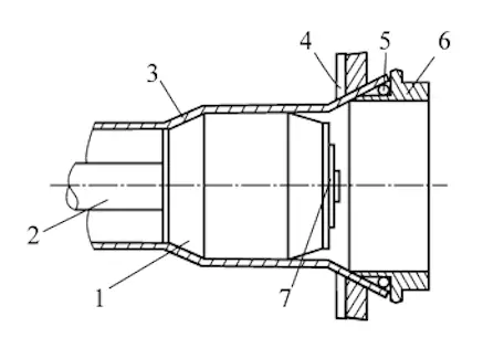
In the drawing and expanding process, first insert one end of the blank tube (350–550 mm long) into a slot heating furnace or an induction heating furnace, heat it to above 850°C, and then use a pressure expanding machine to expand the tube end into a trumpet shape. Next, heat the expanded blank tube as a whole, with a general heating temperature of 900–1200°C. Once the blank tube is evenly heated, fix its expanded end onto the inner and outer clamps of the tube expander. A set (usually 3–4) of expanding tube heads with gradually increasing diameters is fixed onto the corresponding pull rods. Driven by the claws, the pull rod pulls the head through the inner hole of the blank tube, which helps maintain the diameter and reduce the wall thickness of the tube. The drawing and expanding process is illustrated in Figure 1. This process has been phased out due to its low yield rate, poor wall thickness accuracy, and subpar surface quality.

1. Expanding head 2. Pull rod 3. Rough pipe 4. External clamping ring 5. Cooling water pipe 6. Internal clamping ring 7. Fixed head retaining ring
Figure 1 The pulling and expanding process
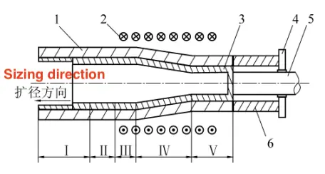
The pushing and expanding process is as follows: the induction coil begins heating from the front end of the billet pipe continuously. When the heating temperature reaches the process requirement (AC3+50–100°C for this steel type), the two oil cylinders on both sides of the push-expanding machine frame synchronously push the push plate placed at the tail end of the billet pipe. The push plate moves the billet pipe forward, causing the heated part to slowly pass through the expanding head, which enlarges the diameter and reduces the wall thickness of the billet pipe. Compared with the drawing expansion process, the top-pushing expansion process does not require pipe-end expansion, and the yield rate can reach 99%. The use of medium-frequency induction heating allows for fast heating and short processing times. The regenerated iron oxide scale on the surface of the steel pipe is minimal, and the outer surface of the expanded steel pipe essentially retains the original surface state of the billet pipe. The inner surface of the billet pipe, coated with graphite lubricant, improves the surface quality. The expansion rate after a single heating is 30–50%, and for low-carbon steel or low-alloy steel with good plasticity, it can reach up to 75%. The expanded steel pipe can have a diameter of up to 1,500 mm, a thin wall, and a diameter-to-wall ratio (D/S) of 70. Currently, the top-pushing expansion process is the primary method for producing ultra-large diameter thin-walled hot-rolled smls pipes.

1. Steel pipe after expansion 2. Induction coil 3. Piercing head 4. Push plate 5. Pull rod 6. Billet pipe I. Straightening zone II. Flattening zone III. Sizing zone IV. Deformation zone V. Guide zone
Figure 2 The process of pushing and expanding pipe
In the stress state of top-pushing pipe expansion, it is observed that when the pipe expands through the inner hole of the billet pipe, there is significant tensile stress in the circumferential direction of the outer wall and considerable compressive stress in the radial direction of the inner wall. Under the influence of circumferential tensile stress and radial compressive stress, the diameter of the billet pipe increases, the wall thickness reduces, and the length shortens slightly. Circumferential tensile stress during top-pushing pipe expansion can easily cause cracks on the outer surface of the billet pipe, and the higher the expansion rate, the greater the likelihood of cracking. If cracks are already present on the surface of the billet pipe, they will expand rapidly, potentially tearing the pipe like an axe, resulting in the pipe body cracking. To prevent surface cracks during pushing and reduce wall thickness unevenness, a billet tube without surface defects and of appropriate size should be selected. The wall thickness of the billet tube during pushing can be calculated by referring to the formula in Chapter 5, Section 5 of Defects and Prevention of SMLS Steel Pipes.
The oblique rolling expansion process includes the rotary rolling expansion process and the secondary oblique rolling expansion process.
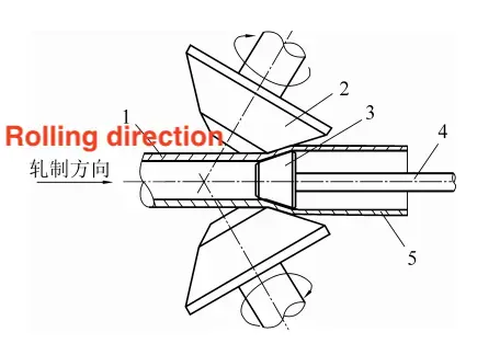
The rotary rolling expansion machine is a two-roller oblique tube rolling machine with two tapered rollers and cross-arranged roller axes. The diameter of the rollers gradually increases from the inlet to the outlet of the deformation zone, and the circumferential speed of the rollers increases along the rolling direction. The axes of the rollers and the rolling line intersect in space to form a feed angle and a rolling angle. Both rollers are supported individually. During rotary rolling expansion, the heated billet tube is fed into the rotating rollers, where the wall is reduced and the diameter is expanded in the "annular closed" hole formed by the rollers, guide plates, and tapered heads. The process of rotary rolling and tube expansion is illustrated in Figure 3. The deformation zones of rotary rolling and tube expansion are divided into three areas: the flattening and reducing diameter zone, the wall-reducing and expanding diameter zone, and the rounding zone. The deformation of the billet tube in the rotary rolling and tube expansion machine includes flattening and reducing diameter deformation, wall-reducing and expanding diameter deformation, and rounding deformation.
Rolling directions

1. Pipe billet 2. Roller 3. Head 4. Push rod 5. Steel pipe after expansion
Figure 3 The rotary rolling and tube expansion process
The diameter and wall thickness of the expanded steel pipe are determined by the roll hole throat size, the head size, and its position. By adjusting the stroke position of the hydraulic cylinder on the push rod tailstock, the wall thickness of the expanded steel pipe can be accurately controlled. Compared to push expansion, the rotary rolling and tube expansion process is more effective at controlling the size of the steel pipe and improving dimensional accuracy. During rotary rolling and tube expansion, the billet tube generates a significant amount of iron oxide scale when heated as a whole. The iron oxide scale on the surface of the steel pipe, especially on the inner surface, is difficult to remove through descaling, and it easily causes "internal pit" defects after expansion. The rotary tube expansion unit is suitable for mass production, but its production cost is high, and it lacks competitiveness. Most products may be replaced by the secondary oblique tube expansion and top-push tube expansion processes.
The secondary oblique tube expansion process is not significantly different from the rotary tube expansion process, except for the mill structure, expansion rate, and selection of billet tubes. During the secondary oblique tube expansion process, perforation and tube expansion are performed on the same perforator. Due to the limitations of the roll shape and adjustment space, the one-time expansion rate is generally not large and does not exceed 30%. In the secondary oblique tube expansion process, the perforated rough tube is returned directly to the front of the perforator (sometimes requiring additional heating), and the wall reduction and diameter expansion of the rough tube are achieved by changing the head size and adjusting the roll position. Because this process allows flexible production and does not require a new tube expander, it has become one of the primary methods for producing ultra-large diameter thin-walled and medium-thick-walled hot-rolled SMLS pipes. The oblique rolling expansion process produces spiral tracks on the surface of the steel pipe due to its deformation characteristics. The greater the expansion is, the deeper the spiral tracks. The depth of the spiral tracks can be reduced by increasing the roll length, improving the re-rolling coefficient, and reducing the diameter expansion rate.


